Systematic Approach to a Precision Polymer Gear Wheel
Published in Kunststoffe international 8/2021, page 54-59
Authors: Wojtek Piecha and Mohammed El Yaagoubi, MS-Schramberg GmbH & Co. KG and Katharina Aschhoff, SIGMA
Optimizing a Tricky Component Geometry Using Sigmasoft Virtual Molding
A great deal has already been reported about the use of Virtual Molding software to plan and analyze injection molding processes from start to finish. However, many people are unaware that this mold can be used to optimize functionality at the design stage. MS-Schramberg, a company specializing in magnets, has a long track-record of developing precision polymer parts for the automotive industry. The following practical example of a gear wheel demonstrates how the efficiency of component optimization can be boosted through the use of simulation.
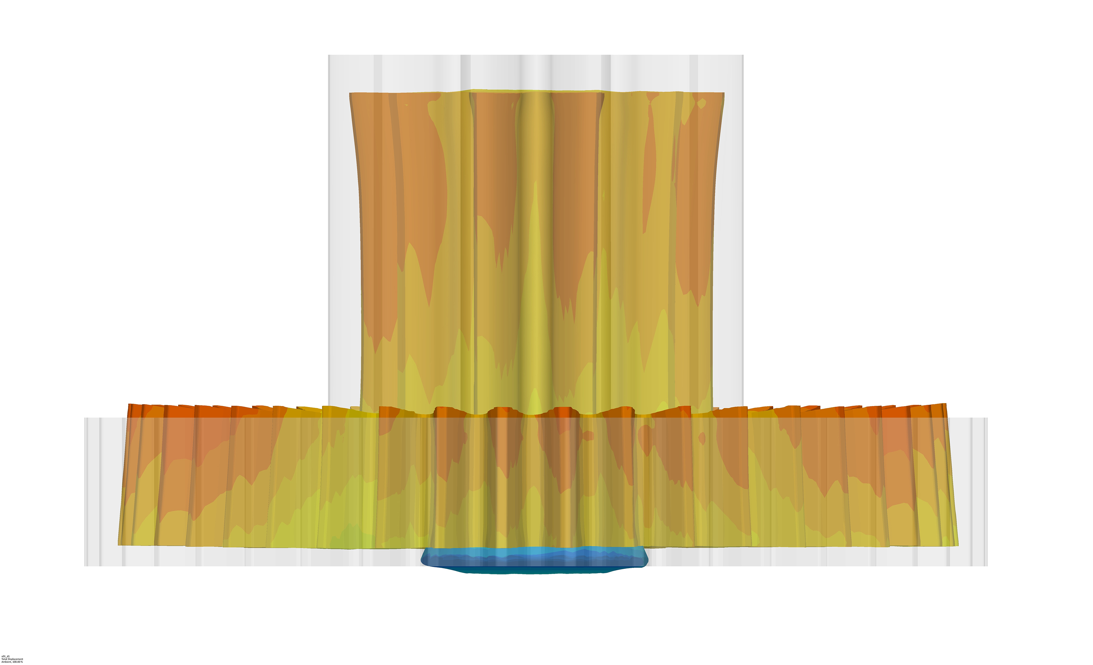
The customer not only specified the geometry of the component by a 3D model but also the polymer to be used, namely a polyphenylene sulfide reinforced with 40 % glass fibers (PPS-GF40). More particularly, the component has a diameter of around 30mm and weighs about 5 g. In the real world of injection molding production, deformation resulting from material buildup, fiber anisotropy and shrinkage poses a risk to the functionality of this gear wheel. A gear wheel that undergoes just radial deformation can be allowed for or corrected relatively easy in the injection mold. However, one that is deformed both radially and axially, as expected in this example (Fig. 1), is difficult to correct in practice and therefore requires careful advance planning.
The goal of this project was therefore to optimize the component geometry – reducing axial gear wheel deformation – even before the injection mold had been made. This was done with the aid of Sigmasoft Virtual Molding software (supplier: Sigma Engineering GmbH, Aachen, Germany). The model was imported into the software, the corresponding negative cavity was created, filled with the designated polymer through manually defined sprue points under application of selected parameters (filling time, temperature, etc.) and then cooled.
Geometry Optimization Necessary
This highly simplified approach proceeds from a constant cavity wall temperature. The complete mold, with its various platens and circuits for heating and cooling, are only considered at a later stage. As a result, the high outlay on modeling and simulation is reduced and hundreds of scenarios can be simulated within a very short time.
Axial deformation of the teeth was minimized by designing a full-factorial virtual test plan designed to evaluate the geometric variation possibilities within the legitimate design space:
- six ribs on the bottom,
- six ribs on the top,
- clearance at the bearing seat,
- radius at the toothing.
Each of these four geometric changes was defined as an activatable input parameter for the optimization process, giving rise to 24 or 16 possible designs.
First Optimization Loop: What are the Major Influences?
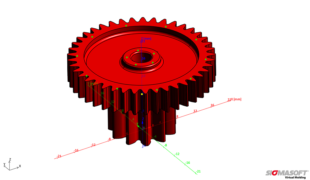
Concrete implementation: in order that the axial deformation of the larger toothing could be determined, measuring points were defined on the toothing and the central running surface (Fig. 2). It was decided that the target criterion representing the optimum solution would be to minimize delta between the axial deformation of the outer and inner reference points as that would yield toothing of good flatness.
It emerged that ribs on the large surface and on the radius on the toothing base offer the greatest potential for improvement. This still left plenty of room for optimization, especially regarding rib design, as so many variables are involved. So, a second optimization loop was then performed to determine the best rib design.
Refining the Result in the Second Step
Again, the aim here was to minimize the axial deformation of the toothing. In addition, for economy, the volume was designed to be as low as possible. The following were varied:
- the number of ribs: between six and twelve, in increments of 1;
- the height of the ribs: between 0.6 and 1.2mm, in increments of 0.1mm, and
- the width of the ribs: between 0.8 and 1.2mm, in increments of 0.1mm.
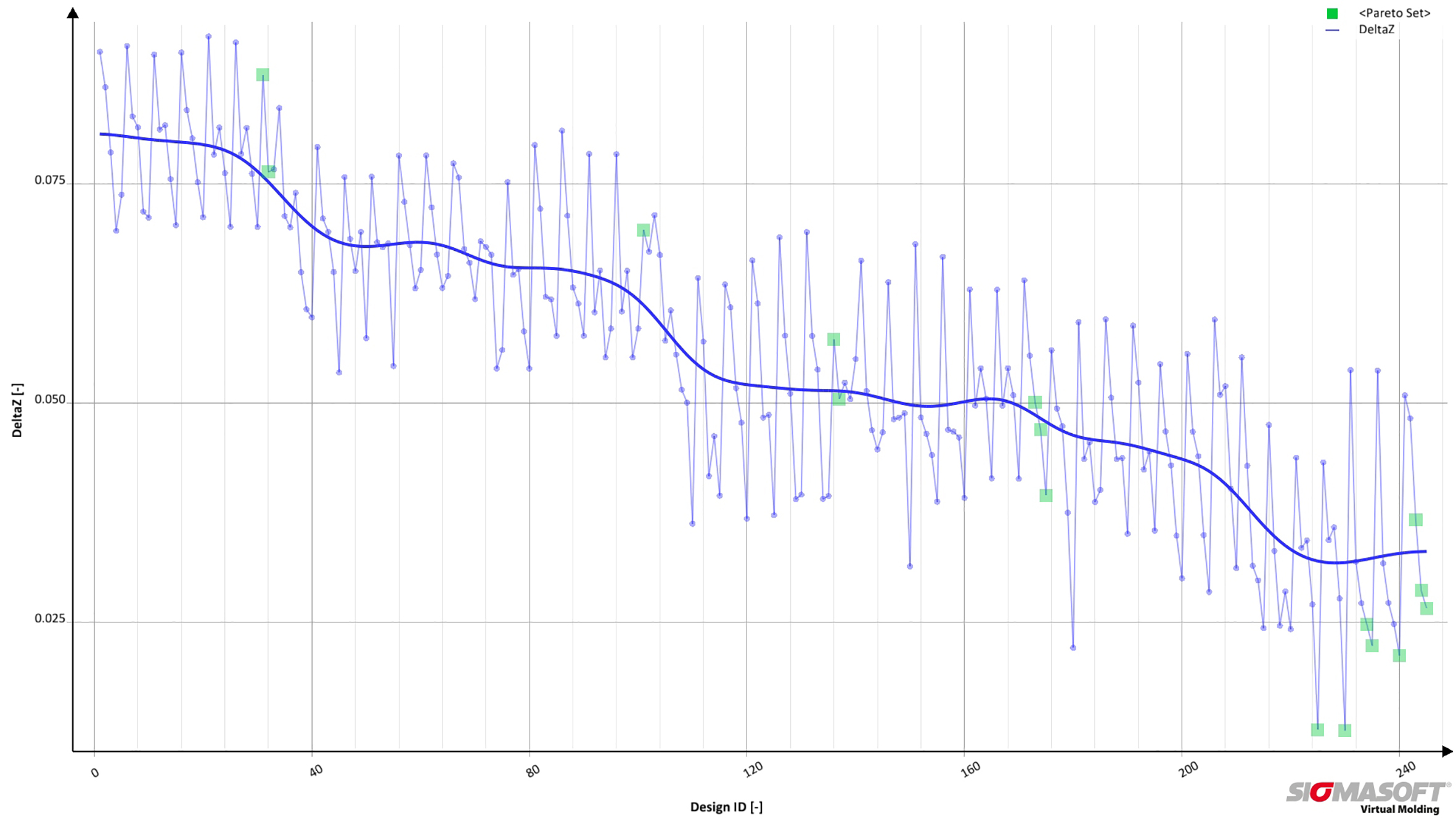
These 7 x 7 x 5 or 245 experiments, too, were subject of a fully automated Sigmasoft DoE (Design of Experiments) simulation. This was done by defining the variables and their values in terms of the respective increments. The entire simulation and evaluation were executed by the system overnight.
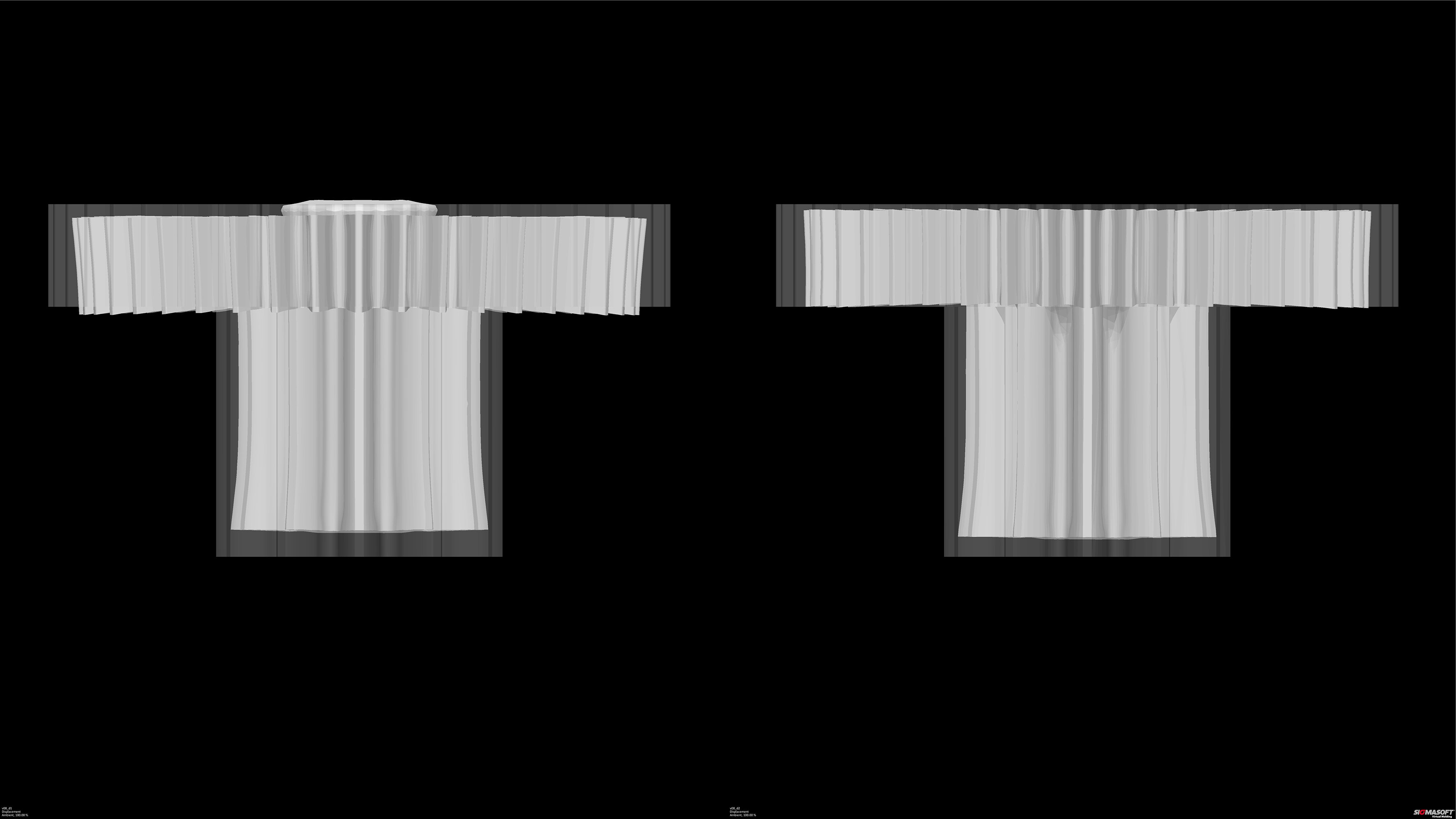
The outcome of the optimization was an enormous improvement – delta Z dropped by about 90 % from 0.19 to 0.02 (Fig. 3). As expected, the solutions offering the greatest optimization potential were those which had the most ribs (twelve). These results were presented to the customer (Fig. 4). After approval had been given, the geometry was updated and the production mold was ordered.
How Many Sprues Are Needed?
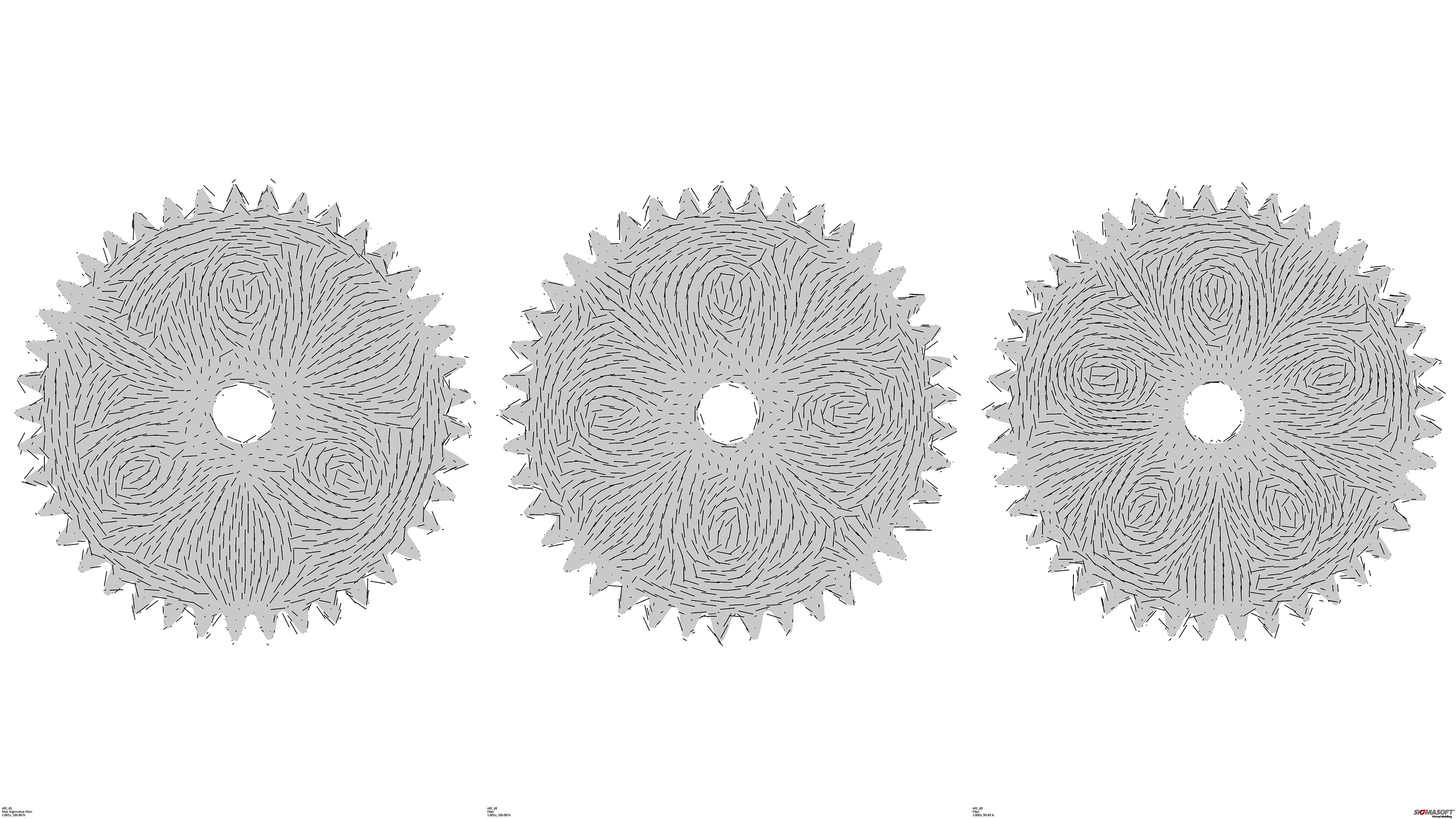
Drawing on positive experience gained by MS-Schramberg in previous similar projects, all the simulations were executed with three sprues on the top. Here, of course, the positive aspect of more homogeneous fiber distribution and shrinkage had to be weighed against the higher mold costs and the cost of material losses. But, again, the simulation is expected to quickly yield an accurate answer. Fiber distribution is determined by the number of sprues (Fig. 5). In each case, differences in the extent of filling lead to differences in shrinkage and warpage. This allows an accurate prediction to be made for each tooth on the circumference.
The simulated axial deformation on the large gear wheel already lay within the target range when three gates were used, with four and five gates offering marginal improvements. For reasons of symmetry, five sprues would of course have been unsuitable for twelve ribs – in this phase, the simulation was executed without ribs (Fig. 6). The next stage was to weigh the necessary functionality and economy against the desired and feasible degree of precision. In the end, the series was realized with three sprues, and was accompanied by a corresponding reduction in material consumption.
Just the Tip of the Iceberg
The case presented here is just one, often forgotten, way of using Sigmasoft software in component and process design. This simulation tool is successfully used, for example, in
- the inquiry phase to rapidly determine cooling times, pressure requirements or to identify critical hotspots early;
- component optimization, as in the case described above;
- mold design to resolve issues with flow paths, thermal layout and sprue positions;
- studies of the behavior of the molded part (weld lines, flaws, fiber orientation, shrinkage and warpage);
- process simulation – here the entire mold is operated over an arbitrary number of cycles. This grants a way of evaluating process capability and stability under series production conditions as early as the design stage.
The DoE method with autonomous optimization that was used here is available for each of these stages and offers a way of systematically and precisely studying all kinds of problems.
Sometimes, though, the results of filling simulations are just a first step towards a reliable solution. Details relating to anisotropic material structure, fiber orientation or the deformed geometry after cooling, as determined with Sigmasoft, can be transferred to other FEA tools for a rigidity analysis, crash simulation or a service life simulation via the existing Sigmalink interface. This allows to determine the limits of a design with even greater precision in a follow-on analysis.
Conclusion
The possibility of activating and parameterizing individual geometry elements allowed a large number of geometric influences to be studied without a great deal of modeling effort. The two optimization loops led to a 10-fold reduction in axial deformation of the large gear wheel. The influence exerted on efficiency by the number of gates was accurately determined.
The simulations executed with Sigmasoft confirmed and extended the high level of development expertise possessed by MS-Schramberg. The documented simulations made a solid contribution to constructive discussions between customer and supplier. The gear wheel went into series production with the simulated changes in a three-platen mold (Title). The optimized quality feature lay within the desired tolerance right from the start.
Although this report merely reveals how to simulate a resilient design with simple tools, Sigmasoft Virtual Molding is then used to design the injection mold and determine the best processing window. Should unexpected problems arise, the tool helps to systematically run through alternative settings, geometry or material changes to quickly arrive at the best solution.

