Inserts d'empreintes, il suffit de les imprimer - Repenser le refroidissement « Conformal Cooling »
Frist published in german at Plastverarbeiter
Justifier la fabrication additive par la simulation ?
La fabrication additive est sur toutes les lèvres depuis plus d'une décennie, et l'impression 3D fait désormais partie des outils de production quotidiens. Outre les prototypes et les petites séries, l'attention se porte désormais sur les opportunités qu'offre cette technologie de fabrication grâce à de toutes nouvelles possibilités en matière de conception et de mise en forme.
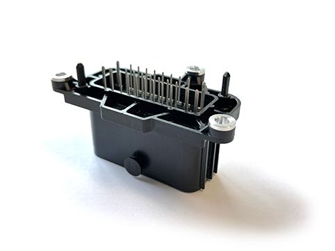
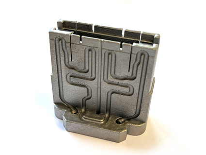
Dans le moulage par injection moderne, un contrôle stable de la température du moule est la condition de base d'un processus robuste et d'une qualité élevée des pièces produites. Le contrôle précis et local de la température influe non seulement sur la durée du cycle, mais aussi sur le retrait et le gauchissement. La conception des canaux de régulation en termes de disposition et de flux doit donc être soigneusement préparée. Pour un contrôle uniforme de la température, il est recommandé de recourir au « conformal cooling » à proximité des parois, mais cette méthode peut s'avérer complexe. Pour une conception détaillée et fiable du moule d'injection et du procédé, des outils de simulation modernes comme SIGMASOFT© Virtual Molding sont indispensables. Le moule, y compris toutes les zones de chauffe, les canaux de refroidissement et les matériaux d'isolation, est représenté virtuellement sur ordinateur avec la matière plastique choisie, en simulant chaque cycle avec précision. Les défauts et les problèmes de qualité sont détectés avant qu'ils ne se produisent. Les modifications et les optimisations peuvent être testées virtuellement avant d'être usinées. Cet aspect est crucial lorsque l'on cherche à compenser les coûts supplémentaires par de meilleurs résultats de production. L'exemple suivant, du spécialiste des connecteurs H&B Electronic, démontre les capacités de la simulation dans le développement d'un système « conformal cooling » innovant et optimisé pour un boîtier de connecteur (voir figure 1).
Où va la chaleur?
Dans le moulage par injection de matières plastiques, la matière fondue est injectée dans un moule d'injection en acier relativement froid (par exemple, à environ 90 °C) à une température spécifique au matériau (pour le PA 66, par exemple, environ 290 °C). Pendant le processus d'injection, la matière plastique fondue commence à transférer de la chaleur au moule d'injection dès qu'elle entre en contact avec la paroi du moule. Ce processus se poursuit jusqu'à ce que la matière fondue se solidifie en un corps solide qui puisse être démoulé. Le moule d'injection doit dissiper la chaleur qu'il reçoit. Cela se fait généralement par des canaux de refroidissement, c'est-à-dire des canaux percés dans le moule à travers lesquels circule un liquide de refroidissement.
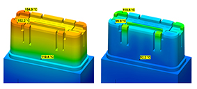
Le flux de chaleur à l'intérieur du moule est influencé de manière significative par deux effets. Premièrement, la quantité de chaleur à dissiper dépend de la géométrie de la pièce moulée. Les zones à parois minces de la pièce nécessitent moins d'extraction de chaleur que les zones à parois épaisses, connues sous le nom de points chauds. Deuxièmement, les canaux de refroidissement percés ne peuvent pas être placés dans le moule de manière à assurer une dissipation uniforme de la chaleur dans toutes les zones de la cavité. Par conséquent, dans les moules refroidis de manière conventionnelle, la répartition de la température n'est pas homogène (figure 2, à gauche). Les zones rouges du noyau présenté ont une température supérieure à 150 °C, tandis que les zones bleues sont à environ 100 °C. Il y a donc une différence de température d'environ 50 °C à l'intérieur de la zone de formage au moment considéré.
La répartition actuelle de la température indique qu'il existe des zones locales à l'intérieur de la pièce plastique qui se refroidissent à des vitesses différentes. Les contraintes internes qui en résultent à l'intérieur du composant conduisent finalement à un gauchissement après le démoulage. En outre, un comportement de refroidissement inégal prolonge également la durée du cycle.
Des améliorations sont possibles...
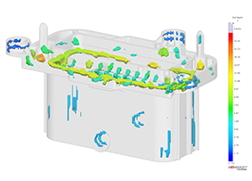
L'objectif du contrôle de la température du moule est donc de minimiser les différences de température à l'intérieur du moule, en particulier dans la cavité, et d'assurer une dissipation homogène de la chaleur. La simulation permet d'identifier avec précision les points chauds (voir figure 3).
Si les points critiques du composant sont connus, la conception des canaux dans le moule peut être adaptée spécifiquement à ces points. H&B Electronic s'appuie sur l'impression 3D de métal pour réaliser des canaux presque librement sélectionnables, proches du contour - nous y reviendrons plus tard.
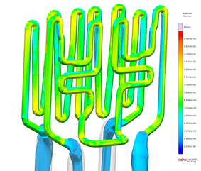
La figure 4 montre une telle conception d'un canal « Conformal Cooling », telle qu'elle a finalement été mise en œuvre dans le moule de série. Le résultat du nombre de Reynolds est indiqué. Pour rappel, un écoulement turbulent, s'il est supérieur à 2300, est souhaitable pour le refroidissement ; un écoulement laminaire, s'il est inférieur, permet un bon transport des fluides. Par prudence, H&B a fixé la valeur limite à 10 000.
Le calcul du débit dans SIGMASOFT est effectué en tenant compte, entre autres, des paramètres d'influence suivants :
- Viscosité du fluide de refroidissement,
- Le débit volumétrique défini en l/min et
- La progression géométrique et la rugosité de la surface des canaux de régulation.
Concevoir le flux à l'aide de la simulation
Les exigences générales pour un système de régulation de la température consistent en une bonne dissipation de la chaleur avec la perte de pression la plus faible possible à l'intérieur du circuit et une distribution homogène de la température dans le composant à un débit donné.
Outre le nombre de Reynolds, la pression requise dans le circuit de thermorégulation est un critère de qualité important (figure 5). Même si la pression requise n'atteint pas une valeur critique dans cet exemple, ces simulations fournissent une aide précieuse pour la sélection du dispositif de régulation de la température et l'évaluation de la faisabilité. Enfin, une faible pression requise signifie également une amélioration de la consommation d'énergie du système de régulation.
Une réduction de la pression requise a été obtenue à travers trois boucles d'itération en mettant en œuvre les mesures suivantes :
- Augmentation significative du diamètre des zones d'entrée et de sortie
- Augmentation du diamètre de l'ensemble du canal de refroidissement
- Réduction ou assouplissement des courbes dans le circuit
Au cours de l'optimisation, la perte de pression a été réduite de 4,5 à 1,8 bar (voir figure 5).
Les images ne montrent pas un tuyau, mais des canaux à l'intérieur d'un bloc d'acier à outils. Sur l'ordinateur, cela semble être une solution parfaite, mais en termes de technologie de production, c'est l'impression 3D qui est utilisée ici en raison de sa faisabilité (figure 6).
L'impression 3D au service de la fabrication de moules
L'impression 3D de métaux était auparavant limitée à l'acier à durcissement par cuisson 1.2709. Ce matériau a tendance à ne pas être utilisé pour les inserts de moule dans la production conventionnelle en raison de ses inconvénients en termes de propriétés thermiques (par exemple, la dureté à chaud) et de résistance à la corrosion. L'acier pour moules à chaud 1.2343 est l'un des matériaux les plus populaires pour de nombreux fabricants d'outils et de moules lorsqu'il s'agit de produire des inserts de moules pour les moules d'injection plastique, par exemple. Il permet un traitement fiable des plastiques techniques en grandes quantités pour produire, par exemple, des connecteurs sophistiqués. H&B est l'un des rares prestataires de services capables de fabriquer de manière fiable des composants à partir de cet acier à outils à haute teneur en carbone en utilisant le processus de fusion au laser (LPBF). En termes de propriétés de matériau telles que la résistance et la dureté, les composants imprimés atteignent des valeurs comparables à celles des composants fabriqués de manière conventionnelle.
Que se passe-t-il ensuite ?
Grâce au « Conformal Cooling », il a été possible d'obtenir une dissipation plus homogène et plus rapide de la chaleur (figure 1, à droite). La simulation avec SIGMASOFT a permis de calculer les avantages du concept de refroidissement pour cet outil et d'autres outils similaires, à tel point que H&B a décidé d'acheter la TruPrint 5000 de TRUMPF. Cette dernière est également disponible pour les projets des clients, tout comme l'expertise interne en matière de conception de moules par simulation. La production de composants hybrides, imprimés sur des structures en acier usinés de manière conventionnelle, est tout aussi possible que la production de composants plus grands (jusqu'à 270 mm de diamètre et 300 mm de haut). La production de ces structures imprimées en 3D n'est pas bon marché, mais elle est généralement rentable dans la production en série grâce à la réduction des temps de cycle et à l'amélioration de la qualité. Grâce à SIGMASOFT, il est possible de quantifier à l'avance les avantages en termes de coûts et de durabilité.
Boîte d'information
Dans le processus de fusion au laser (LPBF), la poudre métallique est fondue couche par couche à l'aide d'un faisceau laser. En outre, l'énergie thermique appliquée localement provoque une nouvelle fusion des zones immédiatement adjacentes qui ont déjà été produites. Le bain de fusion partiel qui en résulte garantit une microstructure homogène et à grain fin similaire à celle de l'acier à outils pour travail à chaud 1.2343 (H11) produit de manière conventionnelle par refonte sous laitier électrolytique (ESR). H&B Electronic imprime exclusivement avec de l'acier 1.2343 (H11) et un préchauffage de la plateforme de fabrication de 500 °C. Cela réduit la tendance aux microfissures et permet finalement de polir les composants imprimés.
Auteurs:
Jan Bayerbach, R&D Manager, /H&B/ Electronic GmbH & Co. KG, Siemensstraße 8, 75392 Deckenpfronn, info@h-und-b.de
Katharina Doetz, Marketing Manager, SIGMA Engineering GmbH, Kackertstraße 16-18, 52072 Aachen, info@sigmasoft.de

